CAN FD - The basic idea
Because of the bandwidth requirements of the automotive industry, the CAN data link layer protocol needed to be improved. In 2011, Bosch started the CAN FD (flexible data-rate) development in close cooperation with carmakers and other CAN experts. The improved protocol overcomes two CAN limits: You can transmit data faster than with 1 Mbit/s and the payload (data field) is now up to 64 byte long and not limited to 8 byte anymore. In general, the idea is simple: When just one node is transmitting, the bit-rate can be increased, because no nodes need to be synchronized. Of course, before the transmission of the ACK slot bit, the nodes need to be re-synchronized.
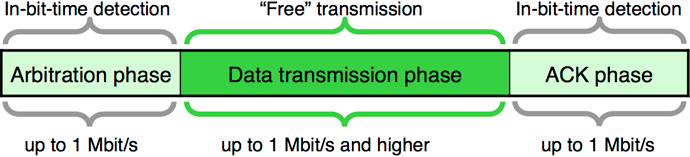
Using a ratio of 1:8 for the bit-rates in the arbitration and data phase leads to an approximately six-times higher throughput considering that the CAN FD frames use more bits in the header (control field) and in the CRC field.
CAN FD – Some protocol details
In order to distinguish between Classical data frames and CAN FD data frames, one of the formerly reserved bits is used. This bit is called FDF (FD frame) bit. If it is of recessive value, the following bit sequence is interpreted as a CAN FD data frame. If it is of dominant value, it is a Classical data or remote frame. In the newly introduced BRS (bit rate switch) bit, the second bit-rate is applied, when it is of recessive (r) value. If it is of dominant (d) value, the arbitration phase bit-time setting is used in the data phase, too.
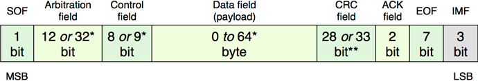
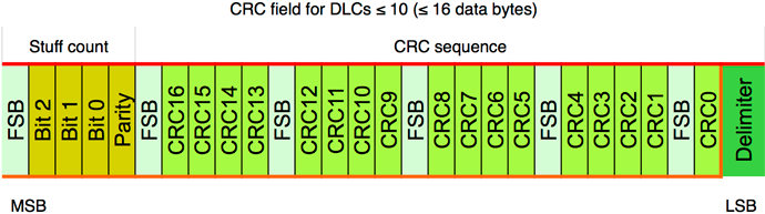
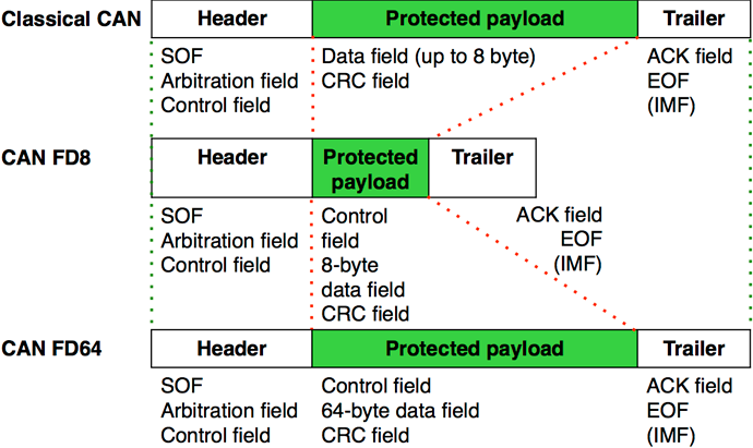
SOF = start-of-frame, CRC = cyclic redundancy check, ACK = acknowledgement, EOF = end-of-frame, IMF = intermission field
The CAN FD protocol controller has to also support Classical CAN frames. Both CAN protocols (Classical as well as CAN FD) are internationally standardized in ISO 11898-1:2015. CAN FD data frames with 11-bit identifiers use the FBFF (FD base frame format) and those with 29-bit identifiers use the FEFF (FD extended frame format). The CAN FD protocol doesn’t support remotely requested data frames.
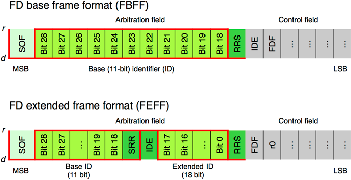
RRS = remote request substitution, SRR = substitute remote request, IDE = identifier extension, FDF = flexible data rate format, d = dominant, r = recessive, r0 = reserved
The control field comprises additional bits not provided by the Classical CAN data frames. The FDF (FD format) bit indicates the usage of FD frame formats. At the sample-point of the BRS (bit-rate switch) bit, the bit-rate switch is performed. This guarantees a maximum of robustness. The following ESI (error state indicator) bit provides information about the error status: a dominant value indicates an error active state.
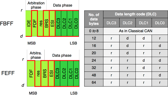
IDE (identifier extension), FDF (flexible data rate format), BRS (bit rate switch; recessive, if alternate bit-rate), ESI (error state indicator; recessive, if error passive)
During the standardization process of the CAN FD protocol, some additional safe guards were introduced in order to improve the communication reliability. This is why the CRC field comprises 17-bit (for frames with payloads up to 16 byte) or 21-bit (for frames larger than 16 byte) polynomials and an 8-bit stuff-bit counter plus a parity bit. The CRC field use fixed-stuff bits (FSB) with an opposite value of the previous bit. All these safe guards guarantee that all single failures are detected under all conditions. Even the possibility to detect multiple failures has been improved.
Medium-term, non-ISO CAN FD controllers might also be on the market – these are not compliant to the ISO 11898-1 standard. They don’t implement the above-mentioned additional safe guard features.